


Underground
Linear Power-Brake Switch
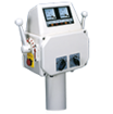
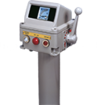
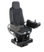
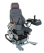
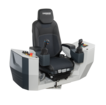
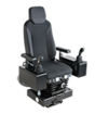
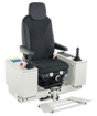
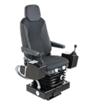
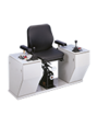
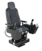
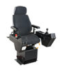
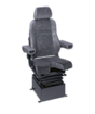
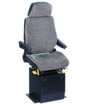
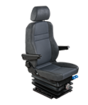
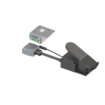
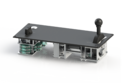
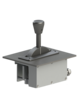
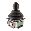
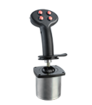
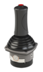
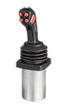
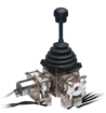
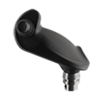
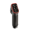
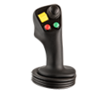
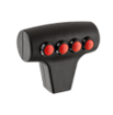
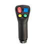
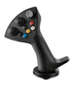
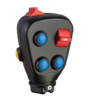
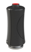
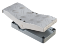
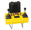
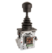
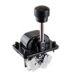
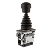
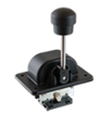
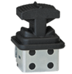
The whole Master Control unit is installed in the driver’s console .
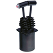
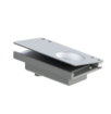
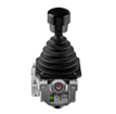
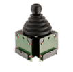
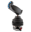
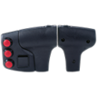
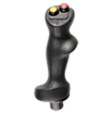
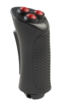
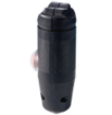
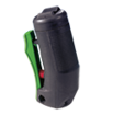
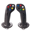
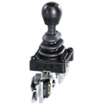
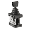
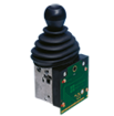
The picture shows the component arrangement and dimensions of the power- /brake control unit which is to be operated by means of a customer specified grip. This grip consists of blank aluminum without any surface treatment.
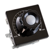
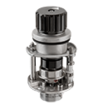
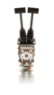
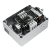
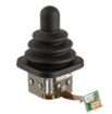
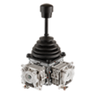
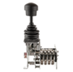
As enlightens from these documents all snap action switches are wired up to a connector that is located at the end of flexible connecting cable. A strain relief makes sure that the connecting cable is properly fixed to the power- / brake control unit. The length of the flexible connecting cable can be adapted according to the project specific requirements. The appropriate mating connector is included in the scope of delivery.
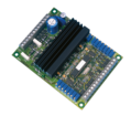
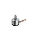
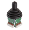
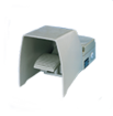
A special connecting cable provides the electrical connection between the capacitive sensor, the potentiometers (which are part of the power- / brake controller) and the interface module that incorporates the following functions:
A 72V to 24 V DC/DC converter Two independent 4 – 20mA output devices. The output device of the capacitive sensor which is used for automatic vigilance control (deadman system) Technical data Power- / brake control unit
mechanical durability 5 Mio. operating cycles
weight approx 10 kg
operating temperature range -25°C to +70°C
maximum humidity during operation 95%
Type tested according to EN 50155
Including
Shock- and vibration test according to IEC 61373
EMC test according to EN 50 121-3-2